
| |
| Home |
| About JKC |
| Coating Library |
| Designs |
| Materials |
| Designer FYI |
| Classes |
| Links |
| Contact Us |
THEORY (at normal incidence)
This section is included in this course to give the reader a brief understanding of where optical interference coating designs originate. Many apologies to those who have seen this before either in an Optics or Physics undergraduate class. These theory sections are relatively brief but they are extremenly important for the student understanding of optical phenomenon at normal and oblique incidence.
Solving for Amplitude Reflectance at Normal Incidence
Let's consider a 3-dimensional Axis...
 Where
the symbols:
Where
the symbols:
¤ = positive y (coming out of page)
Ä = negative y (going into page)
Now let us consider light coming and hitting a surface at normal incidence...
 Where,
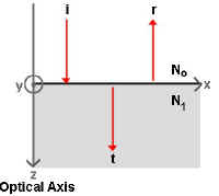
The z axis represents the Optical Axis (or the path of
the transmitted light)
The x axis represents the surface plane between index mediums No and N1.
(this could also be thought of as the plane
between air and a piece of glass)
Imagine a beam of light hitting the surface at normal incidence. The figure includes
the incident ray (i),
the reflected ray (r), and the transmitted ray
(t).
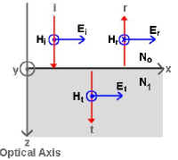
Now, if we include vectors representing the Electric (E)
and Magnetic fields (H) associated with this
beam of light and we respect the Conservation of Energy Law, we see that:
Ei+Er=Et and, Hi-Hr=Ht
(remember that the ¤ represents a positive value, and the Ä represents a negative value)
The Magnetic vector can be represented by the equation:
|
where, |
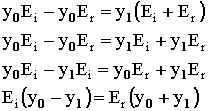
If we consider the amplitudes of the Electric (E) and Magnetic H) fields then,
|
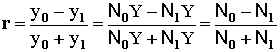
If we combine equations, substituting in for Et and solving for
the
amplitude reflection coefficient (r) where,

we get:
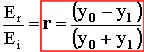
So, we solved for amplitude reflection coefficient (r) in terms of the
optical admittance of both mediums that the light ray comes in contact. We rarely
describe films or substrates in terms of the optical admittance, therefore, we must solve
for r in terms of common values,
such as the complex index of refraction (N).
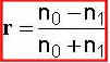
Now, the optical admittance (y) is related to N by:
![]()
where Y is the admittance of free space. So, substituting the above
formula
into the formula for r we get:
The complex index of refraction can be broken down into a real and imaginary component:
![]()
where, n = index of refraction and k = extinction coefficient. k is also the component of the complex index of refraction (N) that represents the inherent absorption in a material.
Now, if we assume that there is no absorption in our films we can solve for the index of refraction (n) by:
![]()
Therefore,
The amplitude transmission coefficient (t) can also be solved in a similar manner by using the relation:

Calculating Reflection & Transmission Coefficients
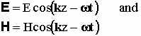
If we have a harmonic, linearly polarized plane wave travelling through free space in the direction of k such that :
We can make the assumption that the energy flows in the direction of propagation of the wave and is given by the Poynting vector (S) where,
![]()
Intensity (I) is the time average value of the magnitude of the Poynting vector. If we solve for the intensity we get:
![]()
Now, if we balance the energy on either side of the boundary we see,
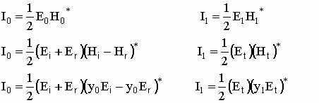
and,
![]()
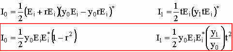
If we solve I0 and I1 in terms of r, t and Ei, we then have:
Now the intensity of the incident beam (Ii) is given by:
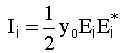
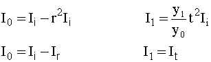
and I0 and I1 can be solved in terms of Ii:
Now, we define Reflectance (R) and Transmittance (T) as:
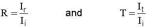
So, solving for R and T we get:
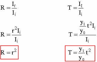
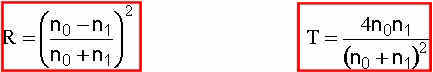
And we remember from solving for both r and t (in your exam) in terms of the index of refraction (n), so therefore:
Back to the TOP