| |
| Home |
| About JKC |
| Coating Library |
| Designs |
| Materials |
| Designer FYI |
| Classes |
| Links |
| Contact Us |
THEORY (at oblique incidence)
This section is similar to the normal incidence section, but of course it is for oblique incidence (or light coming in at an angle to the surface). When light hits an optical surface at an angle there are two polarization states of the light reflecting and transmitting that have to be accounted for. This section will review Transverse Magnetic (TM) waves of light, or P-polarized light.
Solving for Amplitude Reflectance at Oblique Incidence (P-polarization)
Let's consider a 3-dimensional Axis...
 Where the
symbols:
Where the
symbols:
¤ = positive y (coming out of page)
Ä = negative y (going into page)
Now let us consider light coming and hitting a surface at oblique incidence...
 Where,
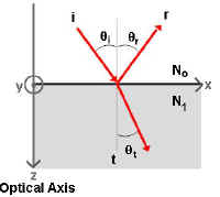
The z axis represents the Optical Axis
The x axis represents the surface plane between index mediums No and N1.
Imagine a beam of light hitting the surface at oblique incidence. The figure
includes the incident ray (i) hitting the
surface at angle qi,
the reflected ray (r) reflecting at angle qr, and the transmitted
ray (t) refracting at angle qt. Where qi = qr.
 Now, if we include vectors representing the Electric (E)
and Magnetic fields (H) associated with this
beam of light and we respect the Conservation of Energy Law, we see that:
Now, if we include vectors representing the Electric (E)
and Magnetic fields (H) associated with this
beam of light and we respect the Conservation of Energy Law, we see that:
Ei+Er=Et and, Hi-Hr=Ht
(remember that the ¤ represents a positive value, and the Ä represents a negative value)
In some textbooks, it is easy to remember the direction of the Electric vector by naming P-polarized light as "Plunging" because the Electric vector looks like it is plunging into the surface.
The Magnetic vector can be represented by the equation:
|
where, |
And, we can relate the Electric (E) and Magnetic (H) vectors to their amplitude components by the following relationship:
Ei=Eicosqi Hi=y0Ei
Er=Ercosqi Hr=y0Er
Et=Etcosqt Ht=y1Et
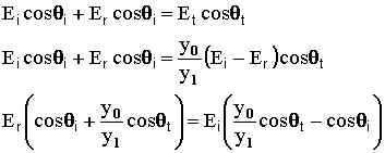
If we consider the amplitudes of the Electric (E) and Magnetic (H) fields then,
|
If we combine equations, substituting in for Et and solving for the
amplitude reflection coefficient (rp) where,

we get:

and we can see from the diagram at the top of the page that
![]()
so,

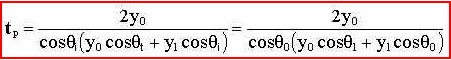
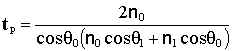
Similarly, you can solve for the amplitude transmission coefficient for s-polarized light (tp) with:
![]()
where we get:
So, we solved for r and t in terms of the optical admittance of both mediums that the light ray comes in contact. We rarely describe films or substrates in terms of the optical admittance, therefore, we must solve for r and t in terms of common values, such as the complex index of refraction (N).
Now, the optical admittance (y) is related to N by:
![]()
where Y is the admittance of free space. So, substituting the above
formula
into the formula for r we get:

The complex index of refraction can be broken down into a real and imaginary component:
![]()
where, n = index of refraction and k = extinction coefficient. k is also the component of the complex index of refraction (N) that represents the inherent absorption in a material.
Now, if we assume that there is no absorption in our films we can solve for the index of refraction (n) by:
![]()
Therefore,

and substituting for y in the equation for t we get:
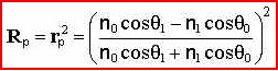
Calculating Reflection & Transmission Coefficients
Solving for Rp and Tp we get: