
| |
| Home |
| About JKC |
| Coating Library |
| Designs |
| Materials |
| Designer FYI |
| Classes |
| Links |
| Contact Us |
Edge Filters
An edge filter is a multilayer coating with a substantial passband on either designated side of the stopband. The edgefilter is meant to have a crisp boundary between wavelength regions that are reflected and those that are transmitted.
This section of the course will be divided into 3 areas:
The Core Stacks - the two basic multilayer edge filter designs.
Combining Core Stacks - this technique will broaden the reflectance area (combining stopbands).
Decreasing
Reflectance in the Passband - this technique will help the designer to eliminate
passband
ripple in the
areas of interest.
There are two basic multilayer designs that are currently used for edgefilters. One design has the passband on the high wavelength side of the stopband, the other on the low wavelength side. The designs are the following:

The designs are illustrated below:

Combining core stacks is a way that the designer can expand or broaden the high relectance region while maintaining the high or low wavelength pass band. The next example includes combining two high wavelength pass edge filters.

Consider the "core stack 1" as a high l pass
design:
(.5H L .5H)10
where the design wavelength is 550nm.
 When
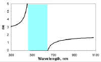
we look at the equivalent index vs. wavelength of the three layers, .5H L .5H,
When
we look at the equivalent index vs. wavelength of the three layers, .5H L .5H,
we can see that there is an undefined area within the high reflectance band.
We will
use this undefined area, called the "stopband" to determine where we locate our
second stack when we combine stacks.

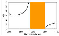
We have a second core stack (red) where the design is:
1.3(.5H L .5H)10
where the design wavelength is the same as the previous design.

As we scale the stack up in wavelength, the stopband will increase in size, slightly.

If you design an overlap of stopbands between each stack, you will
minimize
any leak within the high reflectance zone.

The combination of both designs gives the black line:
Air / (.5H L .5H)10 1.3(.5H L .5H)10 / Glass
NOTE: The core stack that has the lower wavelength
stopband should be placed on top to prevent reflectance loss due to scatter.

If we combine core stack 1 with another stack with less overlap (red) of the design:
1.4(.5H L .5H)10
We can see where the stopband will fall when we plot equivalent index vs. wavelength.

We can also see there is no overlap between stopbands for this example.

Since there is no overlap, a small leak will be created in the high reflectance zone (black curve).
Decreasing Reflectance in the Passband
As a designer works with edgefilters, there may come a time where your specifications dictate that the transmission in the passband be extremely low at a particular wavelength. Knowing that you will come across this issue in the future, it is important that you can complement your edgefilter with some simple refinements that can help you meet these requirements.
![]() The rest
of this section is under construction
The rest
of this section is under construction